
Tech
These are the first projects I made with my Arduino
I just got my first Arduino board and have already been having a ton of fun with it. Of course, I started with the simple projects so I could learn to walk before running. Here are the first three Arduino projects I did, along with the code I used to accomplish each task.
LED flashed up by one pin

One of the first projects that most people do on an Arduino is to light up or flash an LED. It seems ultra-simple because it is.
Wiring up a circuit like this is actually pretty straightforward, as is the code behind it. You can start by flashing the built-in LED on the Arduino board, but I chose to flash an actual LED on a breadboard.
I chose to use a red LED, as the tutorials I was following used that one. I needed a 1,000 Ohm resistor, because the Arduino UNO R4 WiFi that I’m using has a slightly different power profile than the previous UNO R3.
I started by wiring up the simple circuit. I connected pin D13 on the Arduino to the long leg of the red LED. Then, the short leg of the LED got hooked into a 1,000 Ohm resistor over to another set of pins, and then that pin made it back to ground on the Arduino.
The code is also pretty simple. You just have to set pinMode(13, OUTPUT); in the void setup() function, and then toggle digitalWrite(13,HIGH); and digitalWrite(13,LOW); with some delay(1000); between in the void loop() function.
If you’re not sure what the void setup and loop functions are, at a high level, the setup function is code that happens one time when the Arduino boots. The void loop is something that happens indefinitely, looping through until you turn the Arduino off. This is why I set up what pin I wanted to control in the setup function, and I told it to turn on and off in the loop function.
My code for this project is below, so you can see exactly how I accomplished it. You can change pin D13 for another pin if you’d prefer. The built-in LED on the Arduino is set to pin 13, so by programming a physical LED to pin 13, you’ll be flashing both.
void setup() {
  pinMode(13, OUTPUT);
}

void loop() {
  digitalWrite(13,HIGH);
  delay(1000);
  digitalWrite(13,LOW);
  delay(500);
  digitalWrite(13,HIGH);
  delay(500);
  digitalWrite(13,LOW);
  delay(200);
}
Flashing LEDs in sequence

After I got one LED to flash, I worked on flashing multiple in sequence. This took a bit more thinking than just turning one LED on and off, though it used all the same principles that I learned in the first project.
All I did was turn on and off the LEDs in groups. I turned on the first LED, then had a slight delay. Then I turned on the next LED, and had a shorter delay. After that, I turned off the first LED and turned on the third LED at the same time, before repeating that sequence. Eventually, the LEDs looked like they were chasing each other.
I didn’t use addressable LEDs or have to write complicated code to accomplish this task. I simply wired up four LEDs in the same way as I did for the first one—long leg to one of the digital pins on the Arduino, short leg to a 1,000 Ohm resistor. However, I jumped all four resistors to the negative leg on the breadboard so I could bring just one wire back to the Arduino for ground.
Check out the code I used for this project, dissect it, and learn from it. This was another fun project, and it taught me a good bit about C/C++ and the Arduino, since I figured out how to program my own pins into the void setup() function and how to use the delays to space out triggers.
void setup() {
  pinMode(2, OUTPUT);
  pinMode(4, OUTPUT);
  pinMode(6, OUTPUT);
  pinMode(8, OUTPUT);
}

void loop() {
  digitalWrite(2,HIGH);
  delay(100);
  digitalWrite(4,HIGH);
  delay(100);
  digitalWrite(2,LOW);
  delay(50);
  digitalWrite(6,HIGH);
  delay(100);
  digitalWrite(4,LOW);
  delay(50);
  digitalWrite(8,HIGH);
  delay(100);
  digitalWrite(6,LOW);
  delay(50);
  digitalWrite(8,LOW);
  delay(100);
}
RGB LED cycling through colors

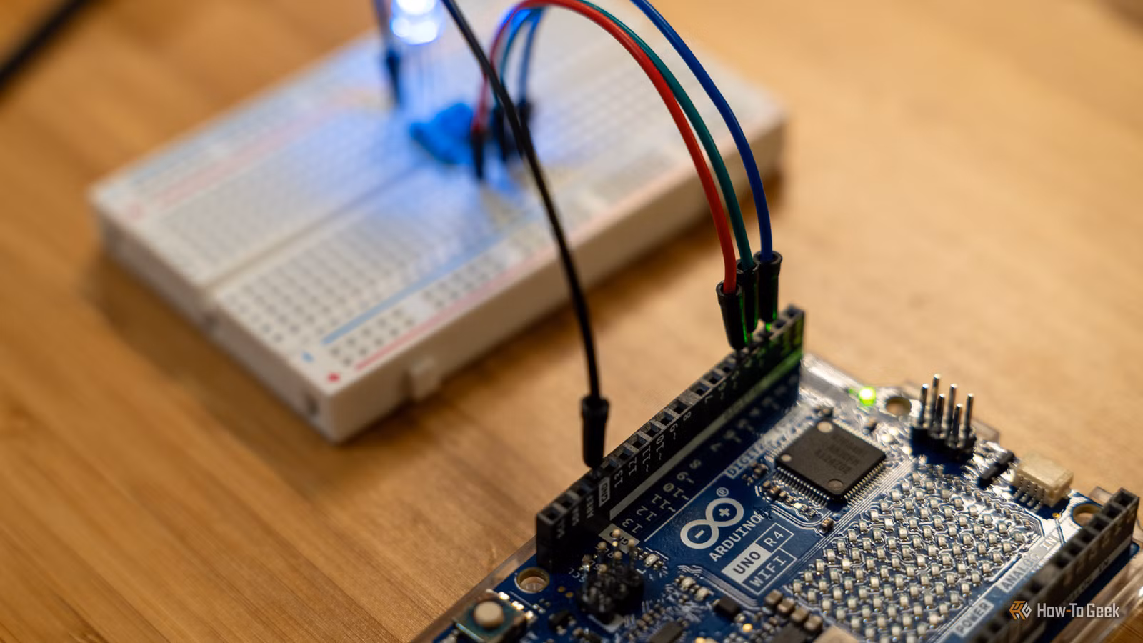
An RGB LED works quite a bit differently than the other LEDs I had used so far, so this took a bit of working on. I adapted my code from the SunFounder documentation (as that was the kit I purchased), and also followed their instructions on how to wire up the LED.
While the other LEDs required a resistor on the ground lead, the RGB LED requires 1,000 Ohm resistors on each of the positive signal leads, and no resistor on the ground. I wired up the blue LED to pin D2, green to pin D3, and red to pin D4.
The code for the RGB LED is definitely a bit more difficult, though, and requires a bit more setup. The start of the code is very similar to the other projects, declaring what pin each color is on, and then setting that up as an output in the void setup() function.
From there, things are a bit different. Since this LED supports multiple colors, the colors are defined with RGB values, 255,0,0 being red, 0,255,0 being green, and 0,0,255 being blue. You’re able to mix these values to create other colors, too. 255,255,0 would create yellow, for example. 255,0,255 would create purple.
The primary colors do have to be set up in another void function below the loop, however. This simply defines what color belongs to each pin, so that the code knows what it’s changing when it cycles through the colors.
That’s it! Here’s my code for you to use and modify however you would like to.
const int redPin = 4;     // Red pin connected to digital pin 5
const int greenPin = 3;   // Green pin connected to digital pin 4
const int bluePin = 2;     // Blue pin connected to digital pin 3


void setup() {
  pinMode(redPin, OUTPUT);
  pinMode(greenPin, OUTPUT);
  pinMode(bluePin, OUTPUT);
}

void loop() {
  color(255, 0, 0);
  delay(1000);
  color(0, 255, 0);
  delay(1000);
  color(0, 0, 255);
  delay(1000);
}

void color(int red, int green, int blue) {
  analogWrite(redPin, red);
  analogWrite(greenPin, green);
  analogWrite(bluePin, blue);
}
These projects were super fun to start with. However, before I got too deep into Arduino projects—simple or not—I 3D printed a few tools to help make my microcontroller programming easier. From jumper wire organizers to PCB holders, you need to 3D print these three tools to make your Arduino projects easier to do.