Tech
A Maker Hand-Wound His Own Robot Actuator, and it Already Moves Real Weight
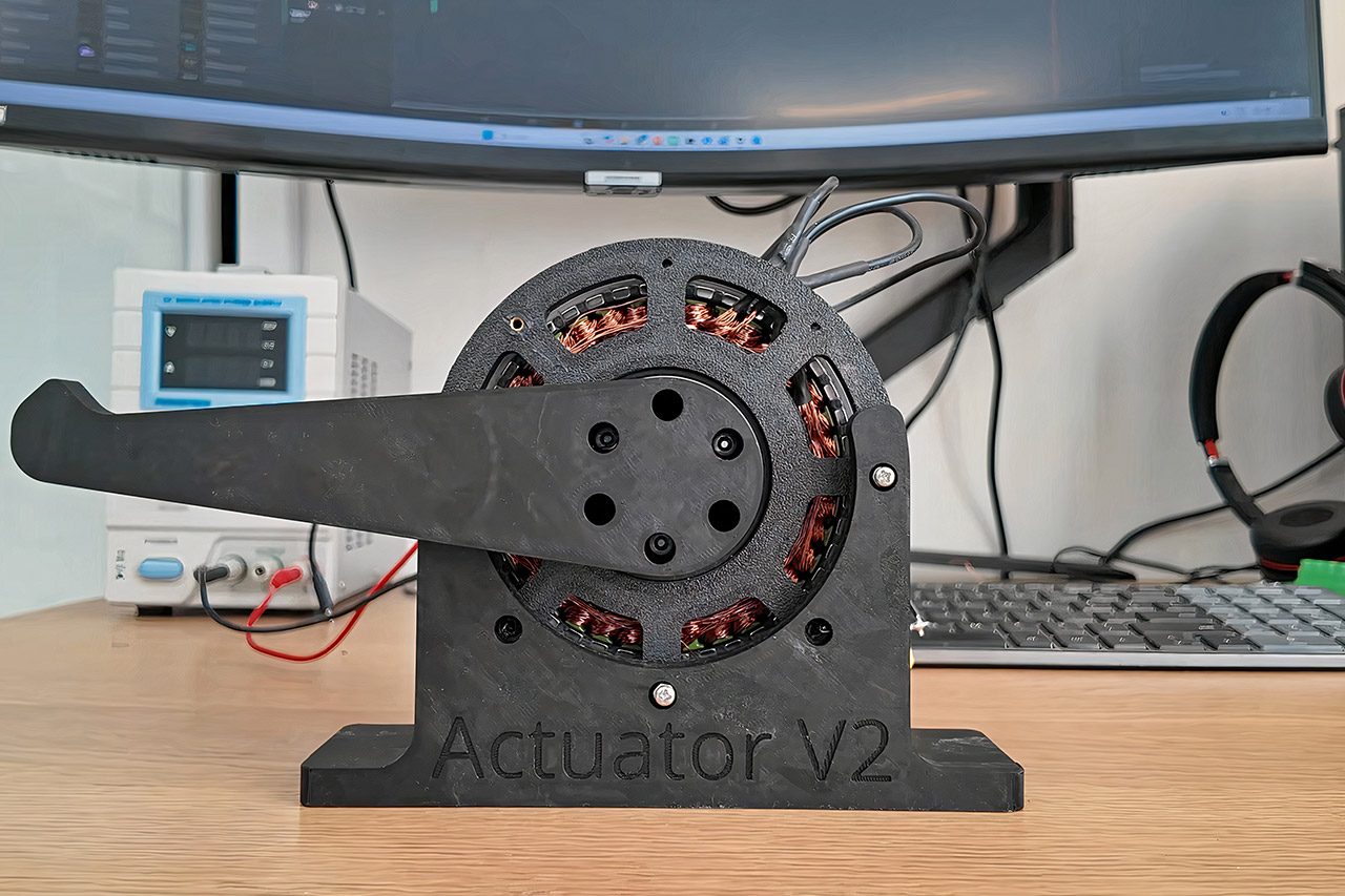
Brandon Lai wants to build a humanoid robot. He started with the upper body and quickly realized that off-the-shelf actuators would either cost too much or limit what the machine could do. So he set out to design and build his own. This latest version marks his second serious attempt, and it already produces usable torque in testing. He focused on a shoulder actuator sized for a roughly four-kilogram arm about half a meter long. The targets were straightforward. Peak torque needed to reach around 20 newton-meters. Output speed should fall between 40 and 60 revolutions per minute. The unit also had to run continuously for more than an hour. Keeping the cost near $150 per actuator would make it practical for other builders to copy or adapt.


The basic design is based on the MIT research into Direct-Drive Actuators, which use a powerful motor and very minimal gearing to maintain the joint feeling snappy while also allowing it to be back-driven by external forces. Brandon admired the spirit of that approach, but chose to make one significant adjustment. He removed the planetary gearbox and replaced it with a cycloidal arrangement. The cycloidal reducer promises more torque capacity in a small space and significantly reduced slop between the input and output.
The motor was built around a normal 110-size stator core from Eagle Power, which Brandon wound entirely by hand. He was able to get 254 twists of copper wire onto the core, divided into six different strands, each with six loops around the tooth. The parallel strands allow the motor to withstand much more current while maintaining a voltage that most controllers can handle. By winding it by hand, he had complete control over the electrical qualities, deciding what it would be like rather of having to go with what came pre-wound.
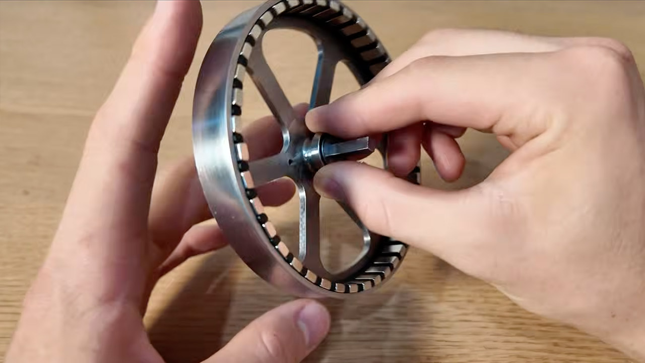
The spinning outer element of the motor, known as the bell, needs to be machined with very precise tolerances. Brandon forwarded the specifications to an online CNC service, and they returned with a smooth stainless steel cylinder ready to be fitted with a ring of powerful neodymium magnets. Brandon set the magnets in an alternating north-south arrangement and sealed them with epoxy after using a simple alignment device. The finished bell is a combination magnetic rotor and primary structural shaft that transmits torque to the output.

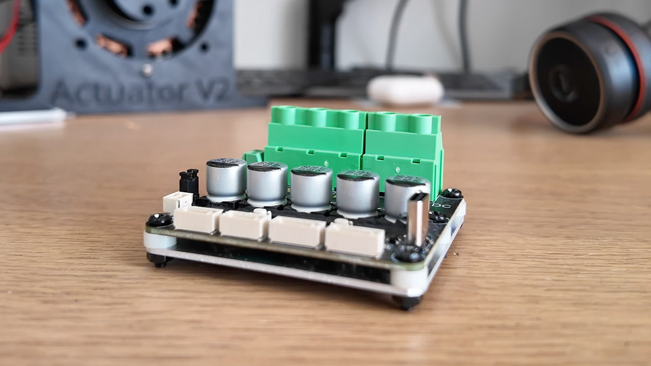
What we’re talking about here is the reduction and torque multiplication that occurs inside the cycloidal gearbox. We get a 10:1 ratio from having an eccentric input turn a lobed disc past eleven fixed pins. The output links directly to the robot arm. Brandon designed and printed the gearbox components for this prototype. This allowed him to make adjustments on the fly throughout development, but it eventually revealed its limitations in terms of precision. Once he acquired all of the elements, such as the motor, bell, and gearbox, he bolted them together around a brushless controller. Initially, he tested a custom printed circuit board that he had designed. Unfortunately, one integrated circuit immediately shorted out and began to smoke. So he swapped in a ready-made Makerbase X-Drive board, which continued to run the motor without issue.
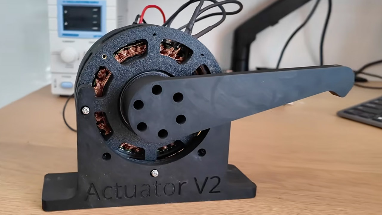
Testing went from the lab to a simple load rig. Brandon fitted a 150mm lever arm to the output shaft and hung a 5kg weight from its end. This generates a torque demand of around 7 newton meters. The power came from a bench supply with current limitations in place. Under those conditions, the actuator was able to support and move the load satisfactorily, delivering approximately 7 newton meters of torque. If we had a supply that could deliver a larger current, we’d almost certainly be able to get even more out of it because torque scales directly to available amperage.
[Source]
You must be logged in to post a comment Login