Tech
Car Alternator Gets Repurposed Into Hydroelectric Generator

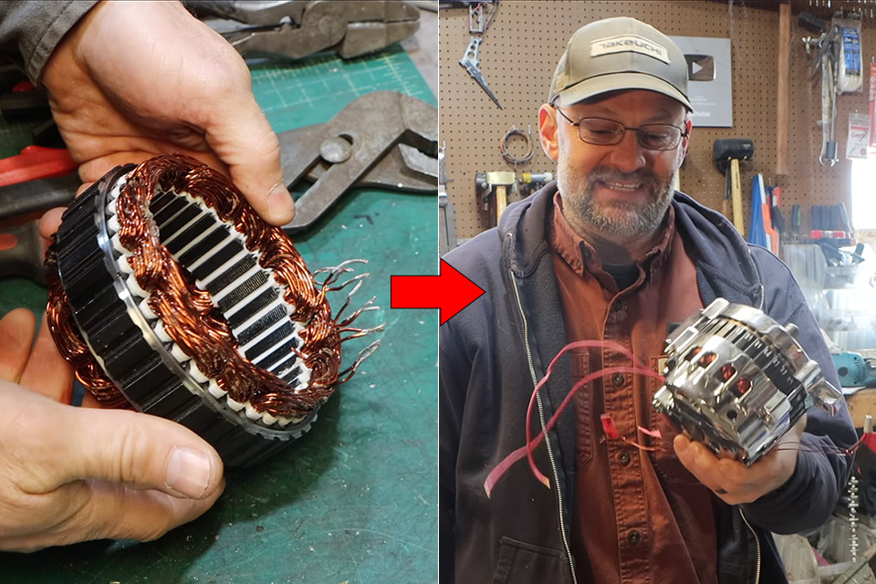
A car alternator will normally charge a battery at 14 volts while the engine is operating. One inventive maker had an epiphany: the same technology might be adapted to do a lot more when connected to running water. John from FarmCraft101 wanted to try his hand at repurposing a conventional car alternator. He disassembled the stator and manually rewound each coil to boost the output to 200 volts, or more if possible. As a result, the technology now powers a piece of his workplace from a pond hundreds of feet away, cutting line losses that would otherwise kill a standard 12-volt system.


Most standard alternators have three-phase AC inside them, but before it is converted to DC, a rectifier inside the alternator is utilized, and a regulator maintains the voltage at a controlled level, roughly 14 volts. We are left with a bare three-phase generator with all other parts removed. The rotor stays as an electromagnet with all parts powered by a small DC supply. When the rotation starts, a current flows through the stator windings. In most alternators, thick wire with a small number of turns per coil is utilized to create a lot of current with low voltage, but John has chosen to use the opposite.


LEGO Technic 1966 Ford GT40 MKII Race Car Building Set for Adults – Collectible Toy W/Realistic Functions…
- BUILD A RACING LEGEND – Relive motorsport history with the LEGO Technic 1966 Ford GT40 MKII Race Car model kit for adults ages 18 years old and up
- REALISTIC FEATURES & FUNCTIONS – Steer using the knob on top, open the doors to explore the interior, lift the engine cover to reveal the V8 engine,…
- AUTHENTIC 1966 DESIGN – This vintage race car model features iconic black and silver design inspired by the real Ford GT40 MKII champion car
He started with a cheap GM CS130 alternator, which he bought online for pennies. The disassembly was straightforward, but once he got to the stator, everything fell apart. The original windings were stuck in a thick layer of varnish and epoxy, and he put the stator in a toaster oven and used a paint remover to remove the original coils. After that, it was just a matter of prying and cutting them out, which took hours.
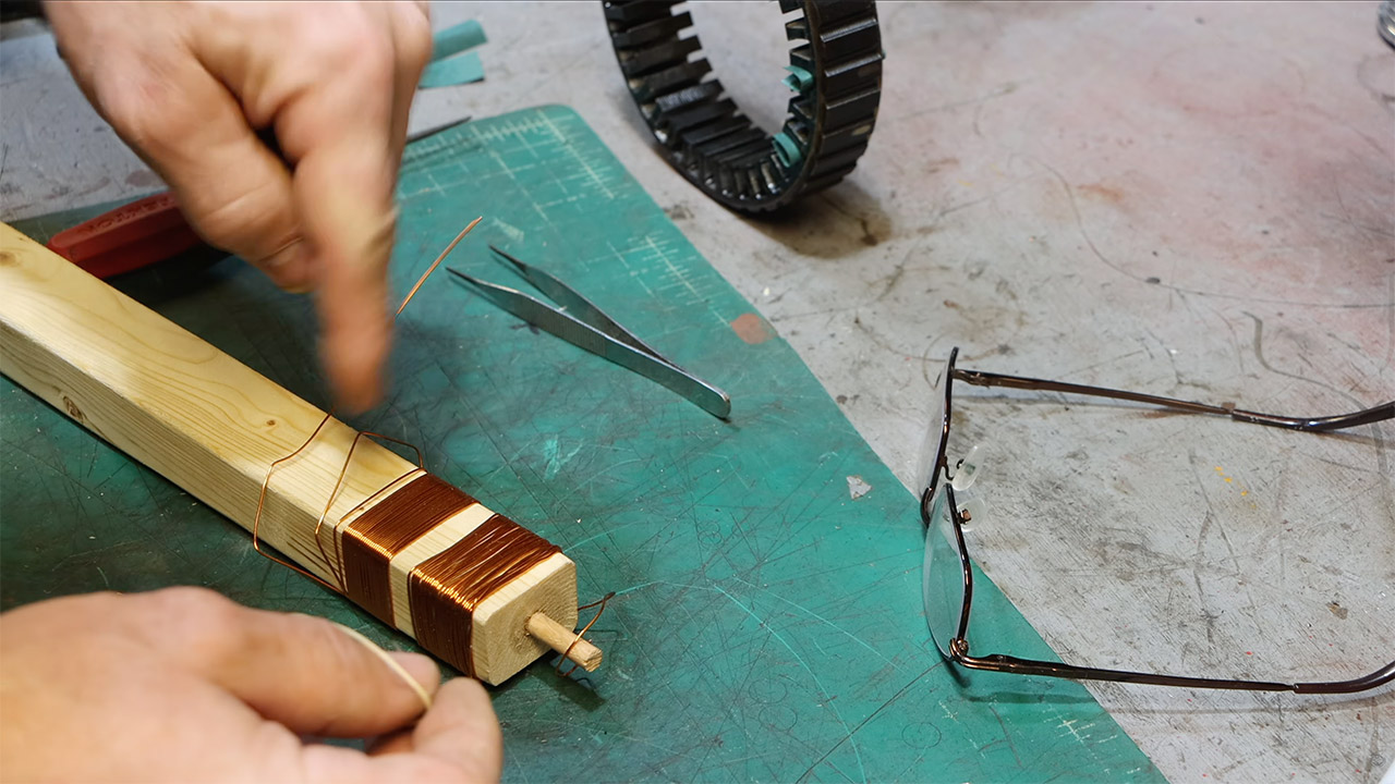
The clean slots were then coated using Nomex paper strips to act as insulators. John then made new coils for each phase using wooden forms and 22-gauge copper wire coated with enamel. The new coils had 30 turns each, unlike the original coils, which had a constant 4 or 8 turns per coil. He made 12 coils per phase, and each phase had 36 slots. Additionally, he made the phases 120 degrees apart to ensure a complete balance in the three-phase current. To do this, he alternated the direction of the coils, causing the north and south poles of the rotor to induce the required current flow.

Once all the coils were installed inside the stator, he made sure to space them out in layers, held securely in place with small 3D printed PETG pieces that simply snap over the holes. Once all three phases were filled in, he connected them up in a star (wye) configuration to increase the line-to-line voltage output rather than trying to increase the current output to its fullest extent with a delta configuration. The reading of three ohms per phase confirmed that the lower gauge wire he had chosen would indeed sacrifice a little current for a lot more voltage.
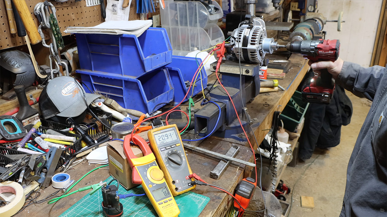
Reassembly restored the rotor brushes, at least for the time being, but he neglected the internal diodes and regulator, intending to compensate by utilizing an external bridge rectifier to convert the three-phase AC to DC. Bench experiments were conducted with an old drill and, later, a geared grinder to spin the shaft up to speed. When the drill got the shaft up to around 1500 RPM, the voltage was around 100 volts with the multimeter set to open circuit mode. Then, as he cranked it up to around 290 volts with the grinder, it became evident that it had a lot of potential. Adding a load of resistors to replicate real-world use, the device produced an astonishing 700 watts. Of course, the voltage sagged slightly under load, but even unloaded, it produced significantly more power than a typical alternator.
John hopes to get roughly 240 volts out of this contraption, which should be enough to power his hydro application as long as the pond turbine spins the alternator at a reasonable rate via the belts. He’ll definitely need to perform some pulley sizing to bring it up to a nice stable 3000 RPM for optimal power. Yes, more voltage implies lower current in the long run to the shop, so he can use thinner, cheaper wire and still transport the same power without wasting it on losses or sagging too far in the first place. He eventually intends to replace the magnetic rotor with neodymium permanent magnets, which will eliminate the need for brushes, excitation power, and other unnecessary complexity.
[Source]
You must be logged in to post a comment Login